Luminaire Manager- Light Source Tab
The Light Source tab contains important information that must be verified for every luminaire family to be used in ElumTools. This information affects the calculation process directly and will vary depending on the architecture of the luminaire family. There are two sub-tabs relative to the light source information: light source Size & Shape and Luminous Area & Color.
Size & Shape Tab
If the luminous dimensions from the photometric file are modified, ElumTools will treat the luminaire as an area source and spread its output across the modified luminous shape. This point is very important as you will encounter families prepared for Revit that do not have the correct symbol size for the IES file assigned. You may also encounter IES files with point source dimensions, even though they are linear or area sources.
IMPORTANT TIPS:
- It is very common to find luminaire families with an improperly aimed light source. Content creators are not always "lighting aware" and do not understand the implications. If the light source is not positioned correctly, it MUST be fixed or your calculations will be incorrect. This is typically a session with the family editor. If you do not understand how to position the source correctly, contact Lighting Analysts Customer Care (help@elumtools.com) for assistance, or contact the manufacturer.
- Verify that the size of the luminous shape corresponds with the luminaire symbol geometry. If it does not, you will need to make a decision to either modify the luminous shape size or leave it as is. As an example, imagine flexed family geometry representing an eight-foot suspended luminaire. Unfortunately, the photometric file is typically tested in a four foot length and does not automatically flex. In this case, it is important to modify the luminous shape to resemble the length of the symbol. If created properly, the family should be 4' long and add sources with each four foot length as it flexes, but this is not always the case. In making this change to the luminous shape, we must also modify the lumen output of the luminaire to resemble two four-foot lengths. This is done on the Description tab.
- As another example where the luminous shape is best left alone, imagine a luminaire with a 2x2 recessed housing. If the photometric file has a luminous shape of Length = 1.5 and Width =2.0, it may be that the luminous area actually only consumes a 1.5 x 2 portion of a 2x2 symbol. In this case, you would make no changes. Needless to say, it is important to be aware of the details when verifying the compatibility of the luminaire family with ElumTools as many families have been prepared for Revit functionality without accurate lighting calculations in mind.
- Another issue that arises with surprising regularity is that of the 1x4 vs 4x1 problem. Linear sources can be photometrically tested with the zero degree horizontal plane of photometry either parallel or perpendicular to the luminaires longer dimension. The "Length" parameter as defined in the Illuminating Engineering Society's document LM-63-02, IESNA Standard File Format for the Electronic Transfer of Photometric Data and Related Information is "...the distance across the luminous opening when measured parallel to the zero degree photometric plane." This will NOT be the luminaires longest dimension if the zero plane is perpendicular as in the case of a wall wash luminaire. This problem is fairly easy to recognize when looking at the photometric web relative to the luminaire geometry and is often a mistake on the part of the content creator. In this case swapping the L and W of the light source is not correct (you are incorrectly changing the source size relative to photometric 0). The proper solution is one of the following. These solutions will require editing the family (unless there same thing can be accomplished by editing type or instance parameters).
- Rotate the light source +/- 90 degrees.
- Rotate the luminaire housing +/- 90 degrees.
- Swap the L and W of the luminaire housing.
Luminous Area & Color Tab
|
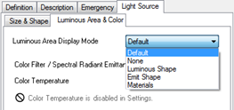
Luminous Area Display Mode
ElumTools allows the rendering of the light source luminous area to be controlled on a family basis from within Luminaire Manager as discussed here, or, on a global basis from the Settings dialog. The display mode selected in Luminaire Manager will take precedence over the selection in the Settings dialog. This allows the default from the system settings to control globally, and luminaire Manager to control locally for only definitions that may function best with a different choice.
ElumTools will display a white luminous area for luminaire symbols in the rendered view based on the setting applied here.
None: disables the rendering of luminous area, this source will appear with standard material colors. Emit Shape: the luminous area will correspond to the shape designated in the family light source definition. Luminous Shape: the luminous area will correspond to the luminous area as extracted from the IES photometric file and possibly modified in Luminaire Manager - Source Position. Materials: the Materials setting will allow you to select a material used in the luminaire family geometry and designate it as "luminous". This can be done in ElumTools Material Mapping by checking the Luminaire Luminous box (Advanced properties) for that material. If the Materials setting is applied and the luminaire has no luminous materials, one of the other modes will be used automatically. If the Revit “Emit Shape Visible in Rendering” parameter is enabled in Settings, the Emit Shape is used. Otherwise the Luminous Shape is used. |

|
Color/Color Output Factor
A Color can be applied to any light source in Luminaire Manager using this setting, (also by editing Revit’s “Color Filter” type parameter). A color filter will behave like a "gel" in theatrical lighting, and will depreciate the lumen output of the luminaire based on the Spectral Radiant Emittance property of the filter color. The calculated factor is determined by the equation found under "Technical Details" in the Luminance Color topic.
You have the ability to override the lumen deration of the Color Output Factor by checking the box and entering your own multiplier. To remove the deration you would most likely enter a value of one.

Color Temperature
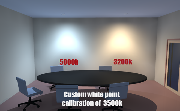
Most luminaire families include a correlated color temperature value (CCT) in degrees Kelvin for the light source. By default, this value is ignored and all rendering is performed with all luminous surfaces using a 6500k white point. ElumTools can render color temperature convincingly and is especially good at showing the apparent difference in different sources in the same scene. The first step is to enable Color Temperature in ElumTools Settings. This is disabled by default.

You can then adjust the family type source color here in Luminaire Manager it if desired. The colors displayed are relative to a 6500k white point so they will look abnormally warm in the color cell.

The Calculation viewer offers the flexibility to change the white point of the rendered display in Display Settings.


